
Complex Geometry Parts
Deep cavities, thin ribs, sculpted surfaces, undercuts and compound-angle bores. Shapes that look clean on screen and get expensive the moment a cutter has to reach them.
This page is about the four things that actually set the price of a complex part — how far the tool has to reach, how sharp the internal corners are, how thin the walls go, and how many times the part gets re-clamped. Everything below follows from those four.
What complex geometry really asks of a machine
A part is not harder to make because it has more lines in the model. It is harder because of four things: how far the tool has to reach, how sharp the internal corners are, how thin the walls go, and how many times the part has to be re-clamped. Material choice matters far less than any of them. XS Precision quotes every job against this list first, which is why two of our quotes can differ from each other: the shape changed.
Those four also explain the thing buyers find most frustrating: two suppliers quoting the same model at very different numbers. The gap is almost never the hourly rate. It is which of the four each shop noticed before quoting — and whether the one that noticed assumed you would pay for a second process, or told you about it first.
So the useful question to ask a shop is not “can you make this”. It is which feature is driving the quote, and what would you change if it were yours. A shop that cannot answer that has not read the geometry — it has priced the envelope. At XS Precision that review runs before the number goes out, because Complex Geometry Parts are exactly the jobs where a quote written without reading the shape comes back later as a change order.
Four things decide what a complex part costs
Nothing here is a rule you cannot break. Each one is the point at which the job stops being routine and starts being engineered.
Read together, they explain why a small part packed with fine detail can cost more than a large, plain one. The big block is one setup, short tools and an open face. The small housing with a deep pocket, a sharp corner and a 0.6 mm wall is four problems stacked in the same 40 mm.
Read the section before you read the price
Take a vertical cut through the part and three numbers decide everything: the entry width, the cavity depth, and the ratio between the overhang and the cutter diameter — the length-to-diameter ratio.
Entry width sets the largest shank that can pass. Cavity depth sets how far that shank hangs out. Put the two together and you get the ratio, and deflection rises with the cube of overhang: double the reach and the cutter moves eight times as much under the same load. That is the physics behind a deep cavity quote, and it is why “just use a longer tool” is never free. XS Precision reads this section off the model before quoting, not off the title block.
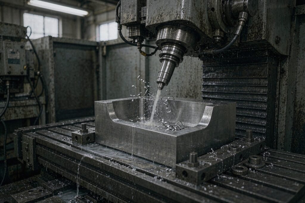
Overhang is the first constraint on a deep cavity
Length-to-diameter is how far the cutter sticks out divided by how thick it is. It is the number a machinist looks at first, because it predicts deflection, chatter and cycle time before any cutting starts.
Deflection grows with the cube of overhang, which is why the step from 4:1 to 8:1 hurts far more than the numbers suggest. On titanium and Inconel the practical ceiling is lower than on aluminium, because the cutting forces are higher and the tool tip runs hotter. XS Precision will say so on the quote rather than quote a ratio that only works in aluminium.
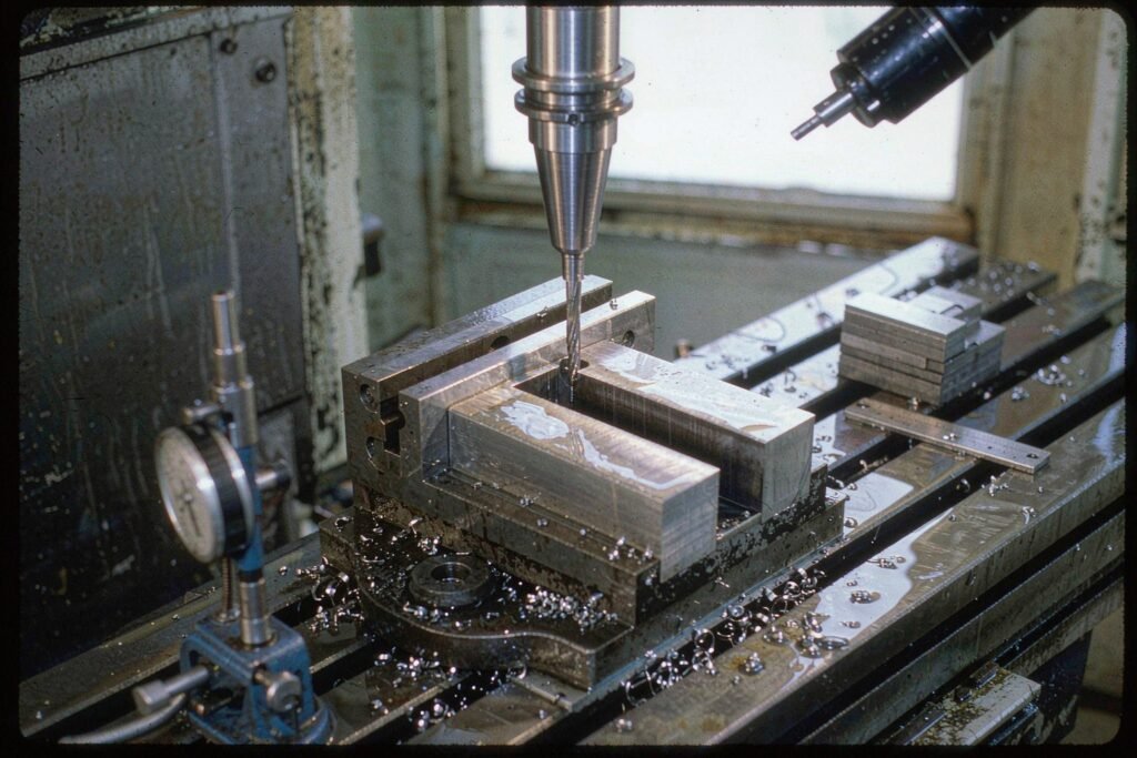
The sharp corner on the print is the most expensive line on it
A milling cutter is round. It turns a corner and leaves a radius equal to its own. Ask for R0 and the shop has two options: creep at it with a tiny tool over many slow passes, or burn the corner in with an electrode. Both are quoted as extra, and both are avoidable.
Two working rules cover most parts. Give the vertical internal radius at least a third of the cavity depth, so a rigid cutter can do the job instead of a micro tool. And make the radius about 15 percent larger than the cutter you expect to be used — that lets the tool roll through the corner at speed instead of decelerating into it, which is what leaves dwell marks on the wall. XS Precision checks both against the model during review and flags any corner that would need a second process.
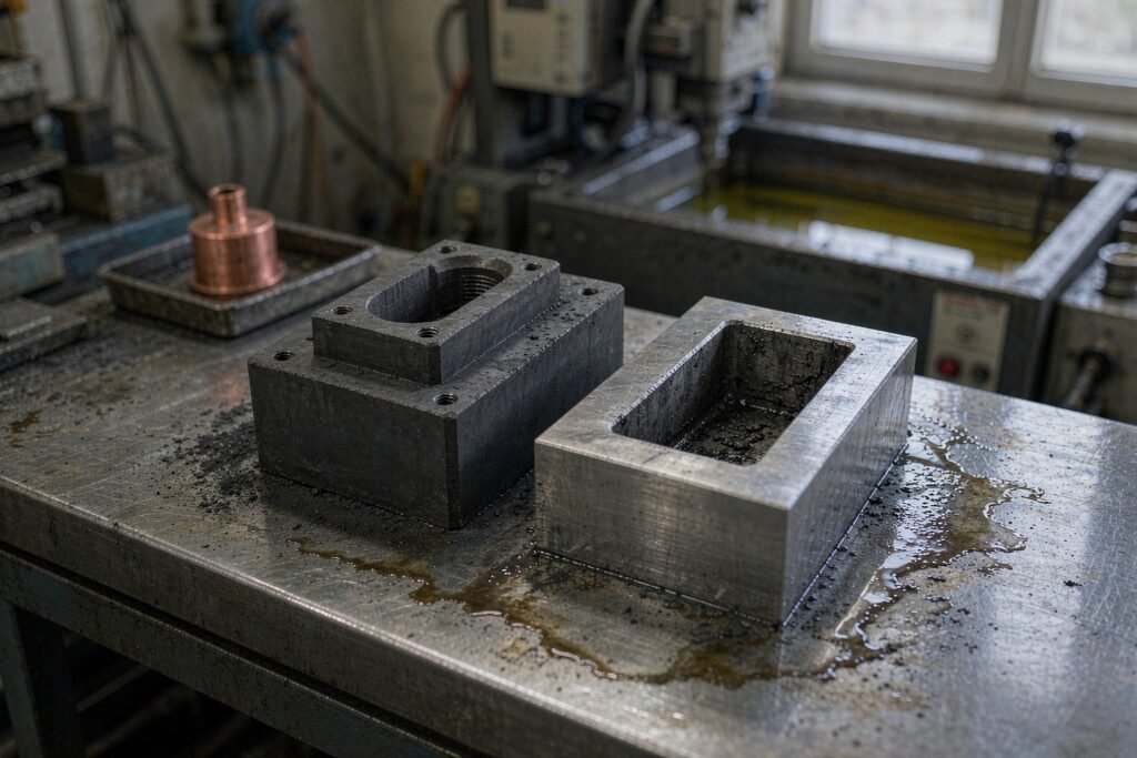
A thin wall is a fixturing problem, not a spindle problem
Thin-wall geometry fails in a predictable way, and it is worth knowing which failure you are looking at. The instinct when a thin wall misbehaves is to slow the spindle down. It rarely works, because the wall is not moving due to spindle speed. It is moving because the cutter pushes it, the material springs back, and nothing is holding it.
Working floors that hold up on the floor: 1.0 mm for aluminium, with 0.8 mm possible only with light finishing passes and dedicated soft jaws; 1.5 mm for stainless; about 2.0 mm for titanium; 1.5 mm for engineering plastics, which move more than metal does. Keep unsupported height under four times the feature width, and add mounting bosses or tabs if the part has no natural place to clamp.
One more thing worth agreeing before the job starts: measure a thin wall after unclamping, not on the machine. A wall that reads in tolerance while it is still held will often read differently once it is free, and that difference belongs to the part, not to the measurement.
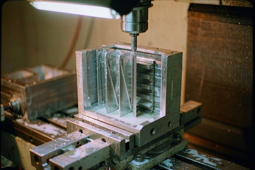
Deep and narrow is two problems at once
A deep narrow pocket makes the tool worse and the chips harder to remove at the same time. Chips that cannot leave get cut twice: they scuff the surface you just finished, chip the cutting edge and push the dimension around over the run.

None of this is exotic. It is the normal tool kit for deep geometry: get the chips out, keep the load constant, and give the cutter an exit. What it does change is the cycle time, which is why depth is quoted before material.
Every setup hands the datum to the next fixture
A part with features on six faces needs six fixtures and six clampings on a three-axis mill. Each one passes the datum from one setup to the next, and that transfer is often the largest single error source on the part — larger than the machine, and larger than the tool.

The crossover is around three or four faces of work. Below that, three-axis is usually faster, because rotary motion and slower feeds on curved paths add cycle time for nothing. Above it, one five-axis setup beats five three-axis setups once handling and re-clamping are counted — and the position tolerance improves at the same time.
Grouping features onto fewer faces is the cheapest change available. It needs no new geometry, no tolerance relaxation and no material change. It just removes setups, and the quote follows. It is also the first thing XS Precision looks for when a complex quote comes back higher than the part looks.
Positional five-axis and true five-axis solve different shapes
“Five-axis” covers two different things, and asking for the wrong one is a common reason a job comes back disappointing. In 3+2 the rotary axes position the part and then lock; the cut itself is a three-axis cut on a tilted plane. In simultaneous work all five axes move while cutting.
The practical takeaway: a deep cavity wall with a taper cannot be finished properly in 3+2, because the tool has to stay leaning while it moves. A hole on an angled face does not need five-axis motion at all — it needs the part tilted once and then held rigidly. Saying which one you need on the drawing saves a round of clarification.
Sometimes the honest answer is a different process
Some geometry is simply not cutting geometry. It can be modelled, it can be rendered and it can be dimensioned, and no rotating tool will reach it. Complex geometry is where a supplier earns or loses trust. Forcing a part through a machine that cannot reach it produces a slow job, a marginal result and a quote that grows later. Saying so early is worth more than winning the order.
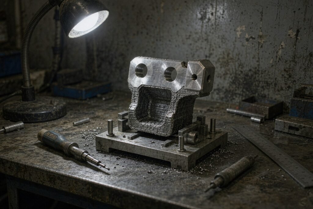
The hybrid route in particular has changed what is worth quoting. Printing a near-net blank and then machining only the surfaces that do real work — the mounting face, the bores, the sealing faces, one datum pad — turns an unmachinable internal shape into a two-day job. The printed surfaces stay as they are; the machined ones carry the tolerance.
Six changes that cost nothing on the drawing and a lot off the quote
None of these needs a redesign. Each is a line on the print or a dimension in the model, and each one removes a process, a setup or a risk that was being priced in. XS Precision runs this list against every Complex Geometry Parts enquiry, and the notes come back with the quote rather than after it.
The tolerance a deep floor can hold is not the tolerance the opening can hold
Tolerance behaves differently across a complex part, and treating the geometry as if it were uniform is a common way to buy scrap. On a deep part, the same nominal dimension is not equally easy everywhere. At the opening the tool is short and stiff; half way down the overhang has grown; on the floor, reach and chips are both working against you. Marking all three the same does not make them equal — it just moves the cost to the hardest one.
Two more things are worth settling before the first chip. Agree the datum scheme on the drawing — a datum chosen because it was handy in the machine will pass inspection and still sit wrong on the product. And keep the drawing and the CAD model at the same revision, because a difference between them is quoted as ambiguity.
What to send for a complex part, and what comes back
Complex geometry is quoted from the model, not from a photograph of it. The more of the following you send, the less the quote has to assume.

What comes back is a quote plus the notes: which feature is driving the number, what we would change and what it would save. On a complex part the first article is not there to confirm a dimension — it is there to prove that this fixture and this tool path produce this shape. The report, the setup record and the material certificate travel with the parts, because on complex work the second batch has to start from what the first one proved. That is the XS Precision default on complex geometry, not an optional extra.
Questions we get about complex geometry parts
Can you machine a part with undercuts?
Yes, but the route depends on the shape. A shallow undercut is reached by tilting the cutter on a five-axis machine. A deep or enclosed one usually is not reachable at all, and then it becomes an EDM operation or a split part. Send the model and we will tell you which one yours is before quoting.
What is the smallest internal radius you can produce?
There is no fixed floor, because it depends on depth. The useful rule is the other way round: make the vertical internal radius at least a third of the cavity depth and a stock cutter can do it at speed. Below that you are paying for a micro tool that runs slow and breaks easily.
How thin can a wall be?
Around 1.0 mm in aluminium is a working floor, with 0.8 mm possible only with light finishing passes and dedicated soft jaws. Stainless sits nearer 1.5 mm and titanium around 2.0 mm, because the cutting forces are higher. Thinner is possible; thinner is not cheaper.
Is five-axis always the better option for a complex part?
No. For a prismatic, open part three-axis is faster, because rotary motion and slower feeds on curved paths add cycle time for nothing. Five-axis wins once the part needs three or four faces, an undercut or a deep wall in one setup.
Why did two suppliers quote the same model so differently?
Usually because they read different things into it. One priced the geometry as drawn, including a second process for the sharp corners and a damped holder for the deep pocket. The other priced an interpretation and will come back later. Ask both which feature drives their number.
Do you need both the 3D model and a 2D drawing?
Yes. The model carries the geometry, and only the drawing can carry tolerances, surface finish, thread callouts and the datum scheme. Quoting from a model alone means guessing at those, and a guess is priced as risk.
What is the realistic lead time for a complex part?
Programming and fixture design come before any cutting on work like this, and that is the part of the schedule that does not compress. A single complex prototype typically runs one to three weeks from a released model, depending on whether special tooling or a second process is involved. We will say which before you place the order.
Complex geometry rarely arrives on its own. It arrives with a tolerance question, a material question or a volume question attached, which is why these pages tend to be read together.
Where complex geometry connects to the rest of the process
Send the model. We will tell you which feature drives the number.
Complex Geometry Parts deserve an answer from an engineer, not a price calculator. Upload a STEP file and a drawing if you have one. You get back a quote and a short list: what we would change, what it would save, and what we would not attempt. If the honest answer is that CNC is the wrong process for your shape, that is what you will hear.