
A prototype is an experiment with a deadline
A prototype is not a small production run. It is a question with a date attached, and the date comes from whatever decision is waiting behind it — a design review, a tooling release, a customer demo. XS Precision machines prototype parts from real stock, in the material on the drawing, on the same machines that run production, and tells you what the drawing will not do before the cutter touches it.
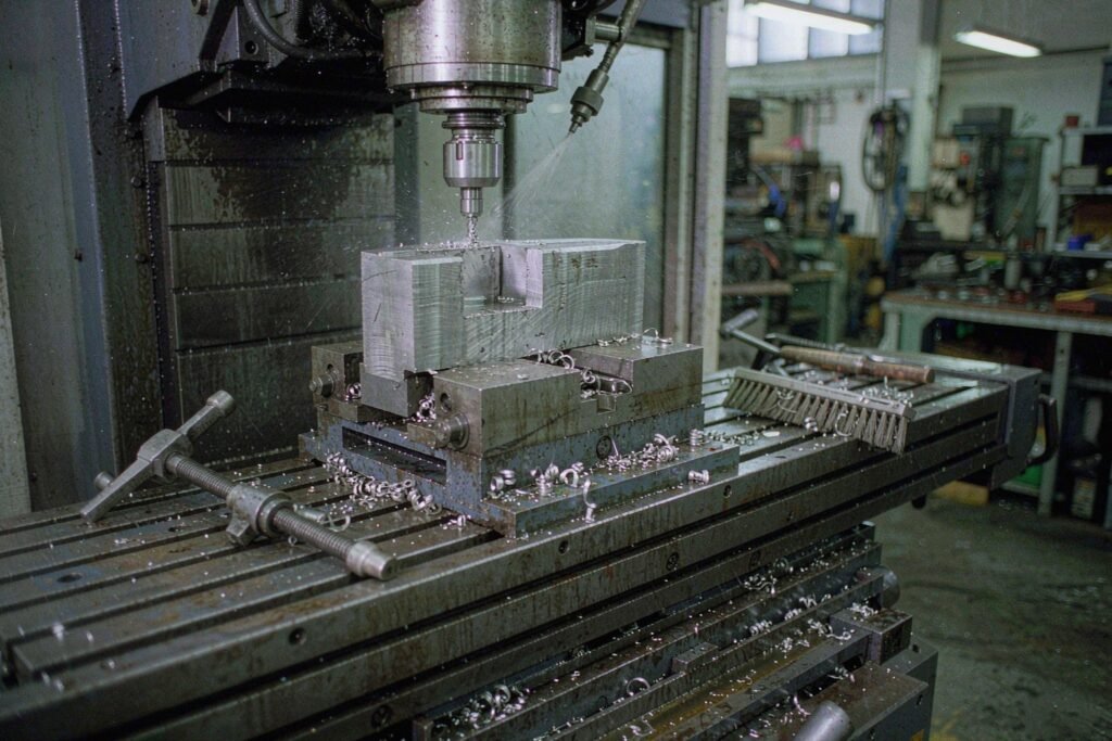
Five questions a prototype can answer, and what each one costs
Different questions need different answers, and each answer has its own price. A founder who jumps from CAD straight to a steel mould is betting a five-figure tooling budget on assumptions that a printed shell would have settled in two days. The reverse mistake is just as common: machining a concept model that only ever needed to be looked at. Decide which of the five questions is open, then pick the route.
The numbers behind that line are not subtle. A design problem that costs roughly $1,000 to fix while it is still a drawing costs anywhere from $50,000 to $500,000 once tooling exists. Each modification after first article typically runs 8–20% of the original tool price and adds two to four weeks on its own. XS Precision runs Prototype Manufacturing as a service in its own right, separate from production machining, and would rather spend your budget on a second prototype than on a second tool repair. The quote will usually show why.
Three prototyping routes with three different sweet spots
The three processes are not competitors. They are stages, and the quantity band each one owns barely overlaps with the next. Pick by quantity first, then by whether the part has to behave like the real thing.

A machined prototype is made of the part, not a likeness of it
When the prototype has to be tested, the material stops being a detail. Machining cuts the part out of the alloy on the drawing, so tensile behaviour, thread strength, press-fit interference and corrosion response are the real ones. Nothing has to be extrapolated from a stand-in.

There is a second reason to cut rather than print when function is the question. Machining shows you the manufacturing reality early: which feature needs a long-reach tool, where a thin wall deflects under clamping, which corner the cutter cannot reach. Those are the same constraints production will face, and finding them on a prototype is free.
A good prototype does not prove you can produce the part
Prototype parts are almost always made differently from production parts, even when the drawing is identical. A skilled operator reads the drawing, compensates for known machine bias, uses general-purpose workholding, takes lighter passes, measures mid-cut and adjusts offsets by hand. The part meets the drawing. The process that made it will not exist at volume.
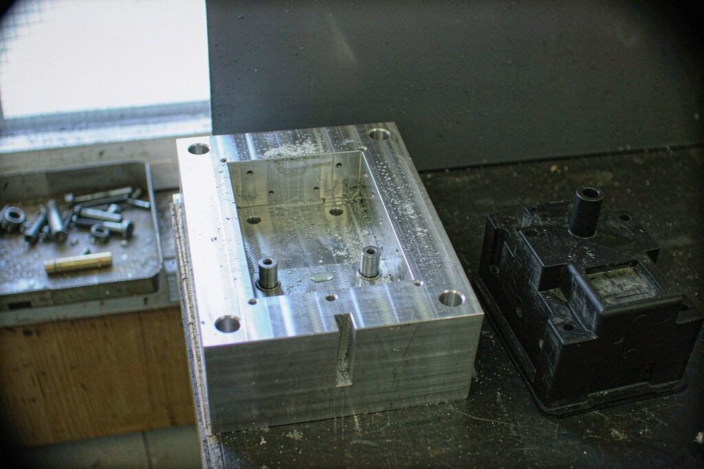
The transition is where the gap between “we can make one” and “we can make them all, consistently, at cost” becomes visible. Tolerance that was absorbed by a careful operator becomes a systematic distribution. A finish achievable with unlimited time cannot be maintained at a production feed rate. A tolerance held on the development machine is not necessarily holdable on the production machine. XS Precision runs a design for manufacturability review on every Prototype Manufacturing order, placed between prototype approval and any production commitment, and aimed specifically at the differences between the two conditions.
From about twenty parts, a cast copy usually beats machining
Between a one-off and a production mould there is a wide band where neither extreme is right. Casting from a silicone mould fills it: one master is made — printed or machined, which is why the earlier routes still matter — then a soft mould is poured around it and copies are cast under vacuum. Fifty presentation units or a pilot run stop being fifty machining setups.
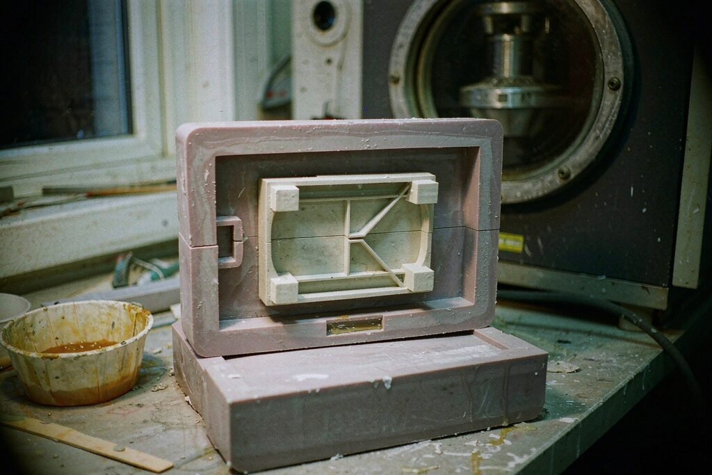
The limits are worth stating plainly. A cast urethane part is not a load-bearing engineering part, and the mould degrades, so late copies differ from early ones. If the run will be repeated next year at the same quantity, a production tool in aluminium may already be the better answer — and that is a comparison we will quote rather than assert.
Tightening the whole drawing is the expensive way to specify a prototype
Applying ±0.025 mm across every dimension when only two surfaces mate is the most common and most costly habit in prototype drawings. It multiplies machining time, inspection time and quote value at once, and it hides real problems rather than solving them: a drawing that tight invites the shop to spend its time chasing dimensions nobody will measure on the production part. Cost multipliers below are relative to the ISO 2768-medium default.
The second trap is a tight tolerance on a feature the cutter can barely reach. It is the most frequent cause of a re-quote, because the original price assumed a tool path that does not exist. If a dimension matters, mark it as critical and leave the rest alone; if it does not matter, the default ±0.13 mm is doing the job already. XS Precision quotes the drawing as written, then shows what the same part costs with the tolerances rationalised — you can compare the two numbers before deciding.
Six things we flag before we cut, not after
A shop that takes the order without comment has either read the drawing very carefully or not carefully at all. Here is what a manufacturability review actually catches on prototype work, delivered as a short list with each quote rather than as a reason to stop.
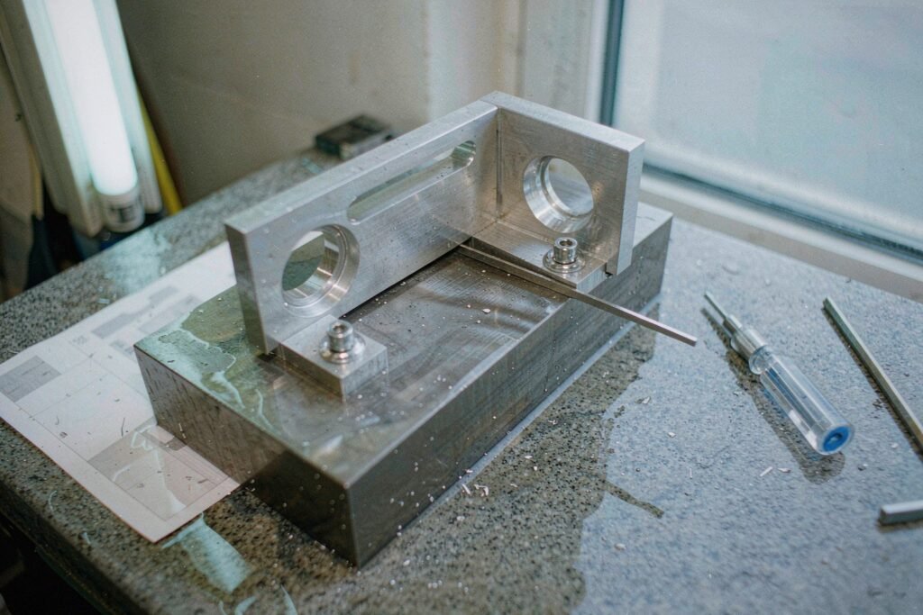
Every one of the six is a document change, not a lecture. We mark the drawing up, say what the change would cost or save, and cut only when the revision is agreed. On a prototype order that exchange is usually finished inside the first working day, which is also the cheapest day to have it.
Six items get you a firm prototype price in one working day
Prototype quotes drift because the scope drifts mid-quote, not because the shop is slow. Send these six and the number that comes back is one you can order against, with the assumptions written down.
The one to two days of programming and workholding cannot be engineered away at any quantity — they are paid once per part number whatever the batch size. The only lever is starting them sooner, which is why the six items above are worth sending in a single message rather than across a week of emails. On a repeat part number, where the program and the fixture already exist, the same work can start on day one.
Four things to freeze before the design leaves the prototype stage
Prototype drawings are usually written loosely on purpose, and that is correct while the design is still moving. The problem is that loose wording travels. A drawing that says “aluminium” is not a specification, and the first sign of trouble is two suppliers quoting the same part 30% apart — one of them is quoting a different material. Before a production purchase order, freeze four things.
XS Precision keeps the prototype program and the production program tied to the same revision number, and records which revision each part in a batch was made to. On a program that moves from five parts to five thousand, that record is what stops a silent dimensional drift from reaching the customer.
A prototype that arrives damaged answers nothing
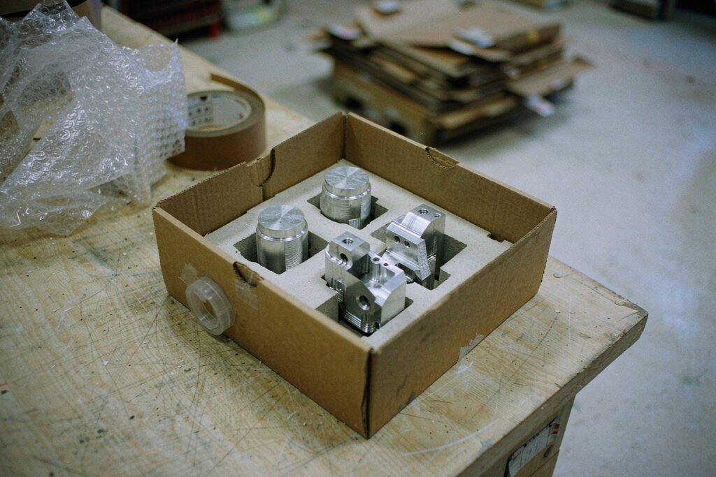
Prototype quantities are small, so packing is often treated as an afterthought. It is not: a hand sample is the only physical evidence a review meeting has, and it usually travels further than a production part ever will — by courier, in hand luggage, through customs. At XS Precision the packing is part of the deliverable, not a step after it.
Questions we get asked about prototype work
Several of these answers cost us the job, which is the point. A prototype ordered on the wrong route is a worse outcome than a prototype we declined to quote.
How fast can you make a prototype?
Standard lead time for one to five machined parts is four to seven working days from a complete drawing, and expedited routing is two to three working days at a 20–30% premium. The clock starts when the model, the drawing, the material and the quantity all arrive together. If the part is complex, has features needing a five-axis setup, or needs heat treatment between operations, it will take longer and the quote will say so rather than promise a date the process cannot hold.
What does a single prototype actually cost?
For a medium-complexity part, machining runs roughly $80 to $600 per part at prototype quantities, driven far more by feature count and tolerance than by size. A printed version of the same geometry can land between $15 and $200. The gap is the price of real material and real tolerance, and it only makes sense to pay it when the prototype has to behave like the production part.
Can you make the prototype in the production material?
Yes, and when the part is going to be tested we will push for it. Prototype and production should share the alloy, the temper and the surface treatment. What they do not need to share is the workholding: a prototype can be cut in a vise while the production part gets a dedicated fixture. Substituting the material is the one shortcut that routinely produces convincing but useless test data.
Should I print a prototype before machining one?
If the open question is form, fit or ergonomics, yes — printing answers it in a day for a fraction of the cost. If the question involves load, wear, temperature or the final surface, no: printed parts are anisotropic, weaker in the build direction, and their layer texture is not the surface you are specifying. Paying for a second prototype is normally cheaper than paying for a wrong decision made from a printed part.
Do I need a first article inspection on a prototype?
Only if your contract requires it. On commercial industrial prototype work, a dimensional report covering the critical features is normally enough, and a full first article with its documentation package would be a significant share of a small order. If your program flows down an aerospace or automotive requirement, the first article is mandatory — tell us when you request the quote so it is in the price instead of arriving as an addition.
How many prototypes should I order?
More than one, and usually more than you first plan for. A single sample gets installed, tested to destruction and never seen again, leaving nothing to compare against. Ordering three to five at once costs very little more than one, because the setup is already paid, and it leaves parts for the test rig, the customer and the shelf. If you are unsure of the final quantity on a part that will be repeated, ask about a quantity break so the second batch does not repeat the setup.
Can you make a part from a sample when there is no drawing?
Yes. Reverse engineering from a physical part, a worn component or even photographs with handwritten dimensions typically takes five to ten working days and can hold around ±0.01 mm on the features that matter. The important part is what happens afterwards: the reconstructed CAD is archived with the part number, so the next order is simply a re-machining job instead of a second reverse-engineering project.
Where prototype work sits in the rest of the shop
Send the part and the decision it has to support.
Send the STEP model, the drawing, the material and the quantity. The quote for your Prototype Manufacturing program comes back within one working day, with the process we recommend, the lead time we can hold, and any manufacturability notes marked on the drawing. If printing, casting or a production route would serve you better than machining, we will say so in the same reply.