
Precision CNC Machining for Optical Systems
Precision parts for imaging systems, measurement equipment, and optical alignment structures. Shenzhen XS Precision machines lens housings, alignment fixtures and structural frames for optical instrument builders — from a first prototype cell to repeat production, on the same fixture and the same programme.
An optical system usually fails at the mechanical part rather than at the glass. A barrel thread cut a few microns off centre tilts the element it carries; a retainer that grips unevenly bends the mirror under it; a housing that grows faster than the lens drifts out of focus as the instrument warms up. XS Precision machines those parts to the datum structure the drawing names, and reports the result.
On lens seats and mount pilots
On locating faces and reference flats
Apply at the stated temperature
The optical axis is set by the housing, not by the lens
Optical drawings normally define three datums. Cell concentricity, element tilt and focus travel are all measured from them, so a part that is accurate but referenced to the wrong face is still the wrong part. XS Precision cuts every datum feature named on the drawing in one setup, and states the temperature the numbers apply at.
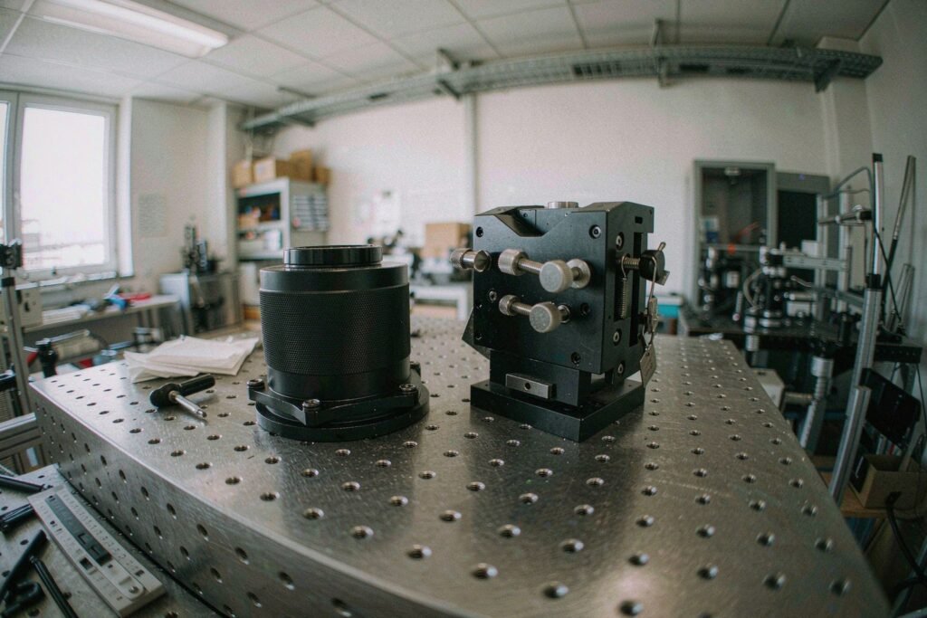
A barrel, a mount and a bench plate referenced to one datum chain stack predictably. Referenced to three different faces, they stack three separate errors.
Lens housings, alignment fixtures and structural frames
Precision parts for imaging systems, measurement equipment, and optical alignment structures. Typical parts XS Precision produces for optical and photonics customers:
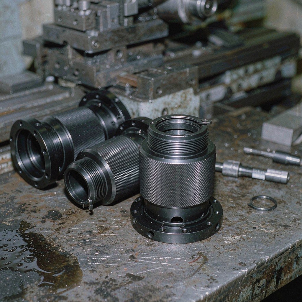
Lens housings
Single-point turned bodies with a stepped bore, lens seats and a retaining-ring thread. Bores are cut before anodising and dimensioned for the film, so a cell seats on metal rather than on coating. Internal surfaces are left dull and dark for stray-light control.
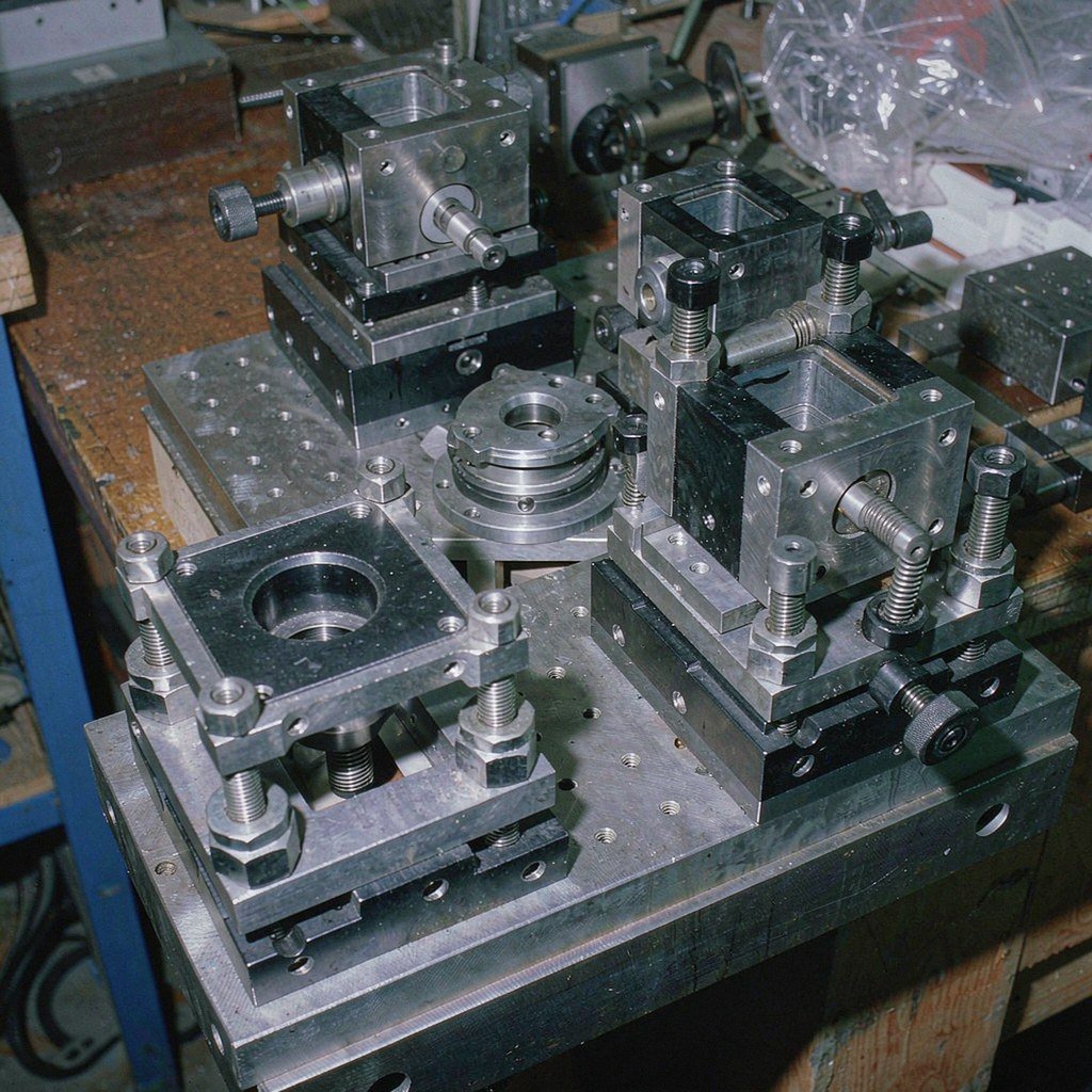
Alignment fixtures
Tip-tilt plates, kinematic mounts, adjuster brackets and calibration targets. Spring plungers, micrometer screws and dowel-pin locations are cut in the same setup as the mounting face, so a mount adjusts smoothly and stays where it is set.

Structural frames
Breadboard bases, cage plates, gantry rails and instrument chassis. Milled faces and hole patterns hold position across the whole plate, so a rail or a stage can be moved and re-bolted without re-aligning the bench.
Parts for a robot arm or a machine pedestal use the same plant and the same reasoning — see the robotics and automation page for how joint tolerance stacks are handled.
Four mechanical faults an optical system cannot correct for
An optical designer can correct aberrations. Nobody can correct a housing that moves. These are the four faults that reach the bench most often, and what changes in the machining as a result.
A thread that runs off centre tilts the element it carries, and tilt costs far more performance than a small lateral shift. Threads are single-point turned in the same setup as the bore instead of being tapped, and verified on pitch diameter rather than on fit alone.
A retainer tightened against a thin wall bends the glass underneath it. Seats are cut square to the bore, wall sections are kept symmetrical round the axis, and contact is spread over a shoulder instead of a corner.
Every machined surface inside a barrel is a chance for an unwanted reflection. Internal bores are cut to a dull finish and black anodised, and baffle grooves are machined in the same setup rather than added at assembly.
Two materials that expand at different rates move the focus point as the instrument warms up. Material is chosen against the glass it sits with, and heavy roughing is separated from finishing by a stress-relief cycle.
The numbers optical drawings usually ask for
Optical work is specified against datum faces, not against a general tolerance block. These are the values XS Precision sources its processes around, and five-axis capacity is what makes the single-setup part of that possible.
Choosing the metal by how it moves with the glass
Glass hardly moves with temperature; aluminium moves about twenty times as much. Where an instrument has to stay in focus across a working range, the housing is chosen against the element it carries rather than against the price of the bar. Figures below are typical linear expansion coefficients, ×10−6 per K.
BK7 borosilicate glass sits near 7.1 ×10⁻⁶ per K, and fused silica near 0.5. A titanium or stainless housing is already within a factor of two of common optical glass; an aluminium one is not. Where the tolerance budget will not absorb the difference, material selection is settled before the first cut, not after the first build.
- Blank stock is stress-relieved before finishing
- Roughing and finishing split by a relief cycle
- Critical features cut after thermal soak
- Mill certificates kept against the lot
What actually ships with an optical lot
A number on a drawing is only useful if somebody can show it was met. Optical lots leave Shenzhen with the dimensional evidence the alignment depends on, recorded against the revision the parts were cut to.
- Concentricity and runout report on lens seats and centring bores
- Surface finish record on datum faces and reference flats
- Thread pitch-diameter verification on barrel interfaces
- First article inspection before a run is released
- Mill certificate and certificate of conformance
- Snag-free packing so a finished face arrives as machined

Interferometric and CMM verification of a machined barrel ahead of release to assembly.
Four stages from drawing review to inspection record
Which faces the optical axis is measured from, which features carry the element, and which are along for the ride. Threads and bores that must stay concentric are grouped into one setup before anything is cut.
One setup wherever the geometry allows, so a bore, its seat and its thread do not pick up a second positioning error. Fixtures are recorded against the part revision and reused on the repeat batch.
Seat diameters, thread pitch diameter and squareness are measured during the cycle rather than after the part leaves the machine, so a drift is corrected before it becomes a lot of scrap.
Concentricity, runout and surface finish recorded against the drawing revision, then packed so a finished datum face does not pick up a handling mark on the way out.
Parts that go straight onto the assembly bench
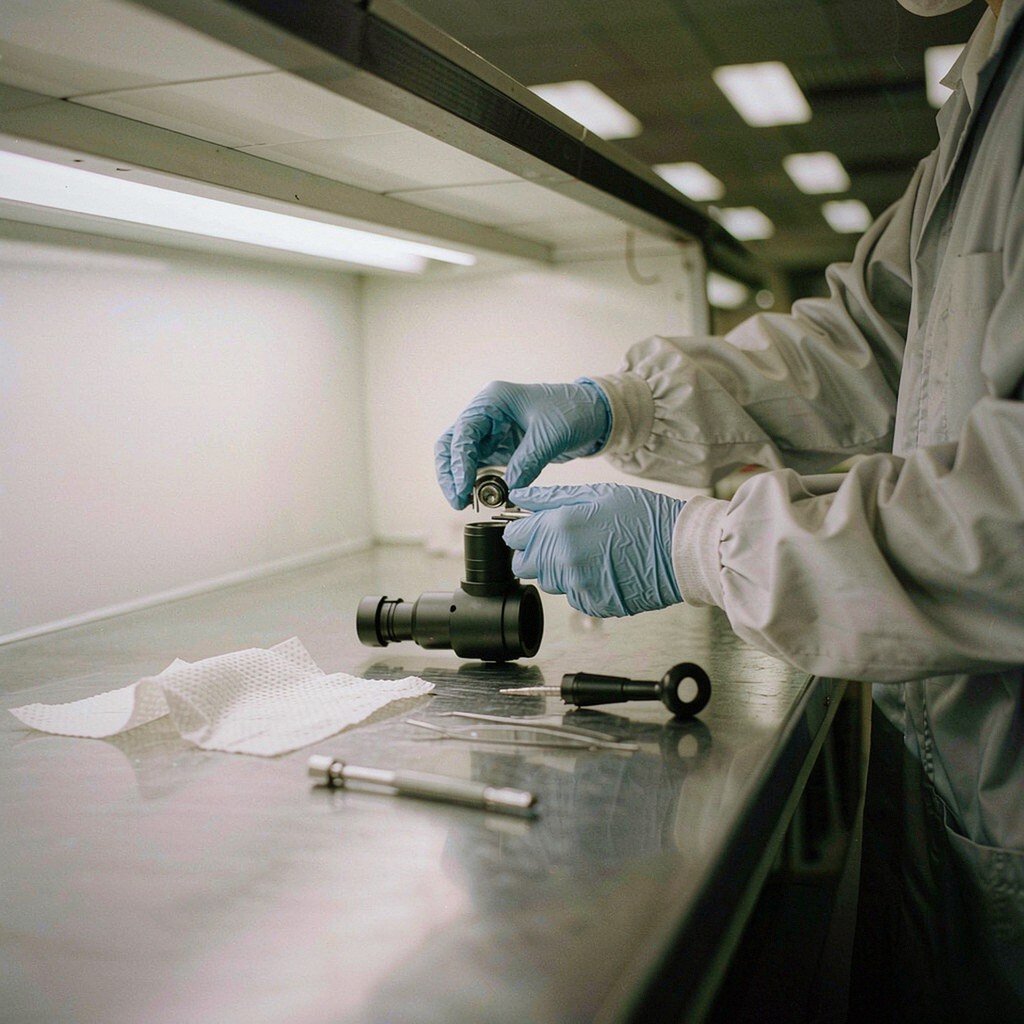
A machined optical part is finished when it is clean, not when it comes off the machine. Burrs, chips and handling marks change how light behaves at the surface, so the last operations on an optical lot are cleaning and packing rather than cutting.
- Deburred and cleaned before it is packed
- Anodising applied after all machining, never before
- Individually wrapped in lint-free material
- No bare aluminium left facing the beam path
- Sub-assembly and careful handling on request
Turned barrels for a camera or a laser module follow the same route as the structural frames around them — see semiconductor work for the tightest cleanliness and finish combination.
Questions optical buyers ask XS Precision
Can XS Precision machine the prototype and the repeat batch?
Yes. Optical programmes move quickly between a bench build and a small production run, so the same fixture, programme and inspection plan carry through from the first article to production quantities. Both are held against your part revision, so a repeat order behaves the way the validated prototype did.
What tolerance can you hold on a lens seat?
Coaxiality and runout on seats, centring bores and mount pilots are held to ≤0.010 mm, with datum faces and reference flats machined to Ra 0.4 µm. Where a drawing calls for tighter concentricity than turning alone will hold, that has to be settled between us before the process is fixed, because it changes the setup rather than just the tolerance.
Do you machine Invar and titanium?
Yes. Invar 36, titanium Grade 5, stainless 303, 316L and 17-4 PH, brass and the usual aluminium grades are all regular stock. Low-expansion and high-stiffness alloys are rough machined, stress relieved and finished in separate operations, because that sequence is what keeps a calibrated geometry from drifting after assembly.
How do you stop stray light inside a housing?
Two things. Internal bores and baffle faces are cut to a dull finish rather than a bright one, and the part is black anodised after machining so the surfaces facing the beam path absorb rather than reflect. Film thickness is allowed for in the bore dimensions, not discovered at assembly.
What do you need in order to quote?
A STEP file or a drawing with the datum callouts, the material, the finish and the quantity. If the drawing shows the optical layout as well, the quote includes a manufacturability review that says which features are going to be expensive to hold and what could be changed before the first cut.
Do you machine optical parts outside Shenzhen?
Yes. Most of the work goes to instrument builders, imaging and laser system manufacturers in Europe, Japan and North America. Quoting, revision control and shipping are handled from the same Shenzhen plant that machines the parts, so there is one point of contact from drawing to delivery.
Send XS Precision the drawing and the datum callouts
A STEP file and a drawing that names datum A, B and C is enough. You get a manufacturability review, a price and a lead time — and if a feature is going to be expensive to hold, you hear it before the first part is cut.