
CNC Machined Parts for Automation Equipment
We manufacture precision mechanical components for automated systems, robotics, and motion control equipment. Shenzhen XS Precision machines mounting brackets, mechanical frames and linear system components for machine builders and system integrators — a first prototype and the repeat batches that follow come off the same fixture and the same programme.
A machine that is aligned on the assembly floor does not stay aligned by itself. It drifts when a rail seat is flat on the bench but not on the frame, when a bolted joint relaxes under a reversing servo load, or when an anodised face comes back 20 µm thicker than the drawing assumed. Most of that is decided before the first chip is cut, in the machining and finishing sequence rather than in the design review.

Three failures that show up a month after installation
Automation parts are rarely rejected at goods-in. They pass inspection, they bolt on, and the cell runs. The complaints arrive later: an axis that binds at one end of its travel, a pick-and-place head that no longer repeats to the number it did during commissioning, a spare bracket that will not sit on the frame the first one was built for.
None of those are design errors in the usual sense. They come from three places: a mounting face that was machined to a general tolerance instead of the number the component on top of it needs, a joint that is allowed to move and eventually does, and two materials that grow at different rates when the cell warms up.
Because Shenzhen XS Precision machines both the component and the face it lands on, the pairing is decided in one place. Rail seats, bearing bores and dowel holes are cut in the same set-up from a common datum, measured on the part rather than sampled from the batch, and reported with the dimensional inspection that the customer’s own assembly team can check against.
Where a feature can only be finished after coating, the drawing says so, the masking plan is agreed at quote stage, and the value on the report is the value after finishing — not the value before it.
What goes wrong, and what we change in the process
Each band below is one problem we are asked to solve, next to the change we make in the machining sequence. They are the three items that come up most often in the enquiries that reach Shenzhen XS Precision from machine builders and integrators.
A base plate milled to a general tolerance looks fine with the rail laid on it in the inspection room. The rail itself is straight to about 0.02 mm over its length, so it is the plate that gives: the rail bows, the carriage drags at one point of travel, and the preload that measured correctly during assembly is gone once a real load is applied.
Rail seats and the faces that locate them are cut in one set-up from a common datum, then measured on the plate itself rather than sampled from the batch. Where a shoulder locates the rail, the seat edge is milled straight instead of being left as the run-out of a corner radius, so the rail can be pushed against a real reference before the screws are torqued.
Bolted frames are adjustable, which is exactly why they move. Under a reversing servo load the joint relaxes, brackets shift a few hundredths, and the geometry dialled in at commissioning is quietly gone. Nothing alarms. The cell simply stops repeating the number it used to repeat.
Where the load path crosses a joint we machine the faces rather than trust an extrusion end. Gusseted brackets are cut from one billet with the bolt pattern and the locating face on the same datum, and dowel positions are held to ±0.02 mm so a rebuilt axis lands where the old one sat.
Aluminium expands at roughly 23 µm per metre per kelvin; a steel rail at about 12. Over a 1.5 m aluminium base plate that is nearly 0.3 mm of difference across a 10 °C shift. Slotted holes and generous clearance hide it at first, and then the reference edge creeps out of position over a season of two-shift running.
We machine to the 20 °C reference the drawing assumes and say so on the report. Where a customer needs the rail to stay put, we machine and mark one end as the fixed datum and leave the other end free in a slot — and we will tell you which face we would use as that datum, and why.
Flatness and position we hold
These are the numbers Shenzhen XS Precision quotes against on automated-equipment work. They are the figures a machine builder can hand to an assembly team without translating them first, and every one of them appears on the report that ships with the parts.
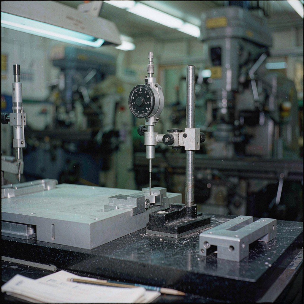
Flatness is checked on the part, not inferred from the machine. A plate that leaves the shop within 0.02 mm over 300 mm gives the rail something straight to sit on.
Frame machining and what the finish takes off
The default for brackets, plates and frames. Stable, anodises evenly, and the cheapest of the options to rework if a revision arrives mid-batch.
For brackets that carry a bending load or a clamping force, and for adapters where stiffness matters more than weight.
Bearing seats and rubbing faces, through-hardened or nitrided where the surface actually wears.
Wash-down cells, food lines and wet environments. Passivated and cleaned rather than painted.
Type II grows the surface 5–25 µm per side, Type III 25–75 µm. Threads, press fits and mating faces get masked.
Steel parts that need corrosion protection without moving the fit. Thickness is stated, so the stack-up still closes.
Anodising converts the surface rather than coating it, so a 20 µm Type II layer turns a 10 mm shaft into 10.02 mm and shrinks every bore it reaches. Dimensions on XS Precision drawings are the dimensions after finishing, critical bores and threads are masked, and the masking route is agreed when the job is quoted instead of being discovered at assembly.
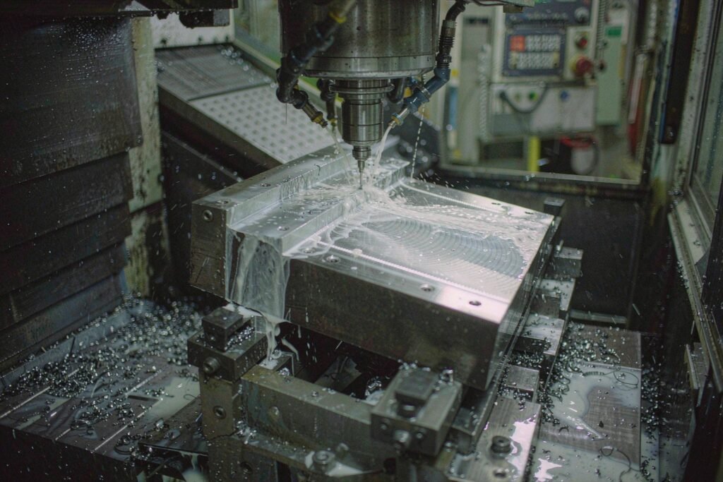
Long frames are roughed, allowed to settle, then finished. Welded assemblies are stress-relieved before the mounting pad is milled, so the pad is still flat a month later.
From drawing to axis assembly
Six steps at Shenzhen XS Precision, the same six whether the order is five brackets or five hundred frames. The right-hand column is what leaves the shop at that step, so a project engineer can see where a build programme sits.
Which face locates the part, which faces are clearance only, and whether the finish value is called out before or after coating. This is where most of the cost of a part is really decided.
A quote with a lead time, plus a note on any feature that will be expensive to hold — a deep pocket at Ra 0.8, or a tight bore inside a thin rib.
The programme and the fixture are built once. The first article is measured and photographed, and the report goes out before anyone has to ask for it.
Roughing and finishing kept in separate operations on long or thin parts, so material is not released into the finish cut. Same tooling throughout the batch.
Masking applied before coating, threads chased after it, mating faces protected for shipping. Parts arrive ready to bolt on, not ready to be cleaned up.
Material certificate, dimensional report, flatness and parallelism results, and the finish thickness record wherever the stack-up depends on it.

A ball screw support housing and a machined carriage plate going together on the bench. Both were cut in one set-up, so the bearing seat and the mounting face already agree.
The three part families, in detail
We manufacture precision mechanical components for automated systems, robotics, and motion control equipment. Everything we make for those systems lands in one of three families — select one to see what it has to hold, and why.
Cut from solid rather than bent or cast, because the bolt pattern has to land in the same place every time. Gusseted L- and T-brackets, sensor mounts with a sliding adjustment slot, motor and gearbox adapter plates, and joining plates for aluminium frames.
On mounting brackets the bolt pattern is held relative to the locating face, not relative to an arbitrary edge, and dowel positions are reamed to ±0.02 mm. That is what makes a bracket ordered six months later interchangeable with the one it replaces — the point being that spares are usually wanted for exactly the part that was ordered the first time.
Base plates, gantry uprights, cross beams and end plates for automated cells. Long parts are roughed, allowed to settle, and finished in a second operation; welded frames are stress-relieved before the mounting pads are milled.
Where the design allows, the rail seats are milled into the frame itself instead of being added as a separate plate. That removes one joint between the motor and the workpiece, and one more place for alignment to be lost. We will say so at quote stage if a design would be stiffer with the seats in the frame rather than on a bolted plate.
Ball screw support housings with a bored bearing seat, a shoulder and a snap-ring groove; carriage adapter plates with a reamed dowel pair; rail spacer blocks; belt tensioner brackets; and end plates for linear modules.
The bearing seat and the face that mounts the housing on the frame are machined in one set-up. That pairing is where most of an axis’ lost travel comes from: cut it in two operations with a fixture between them and the housing still bolts down, it just no longer points where the screw runs.
Three part families we machine for automation builders
The same three families for every customer, machined at the Shenzhen plant and measured before they leave it.
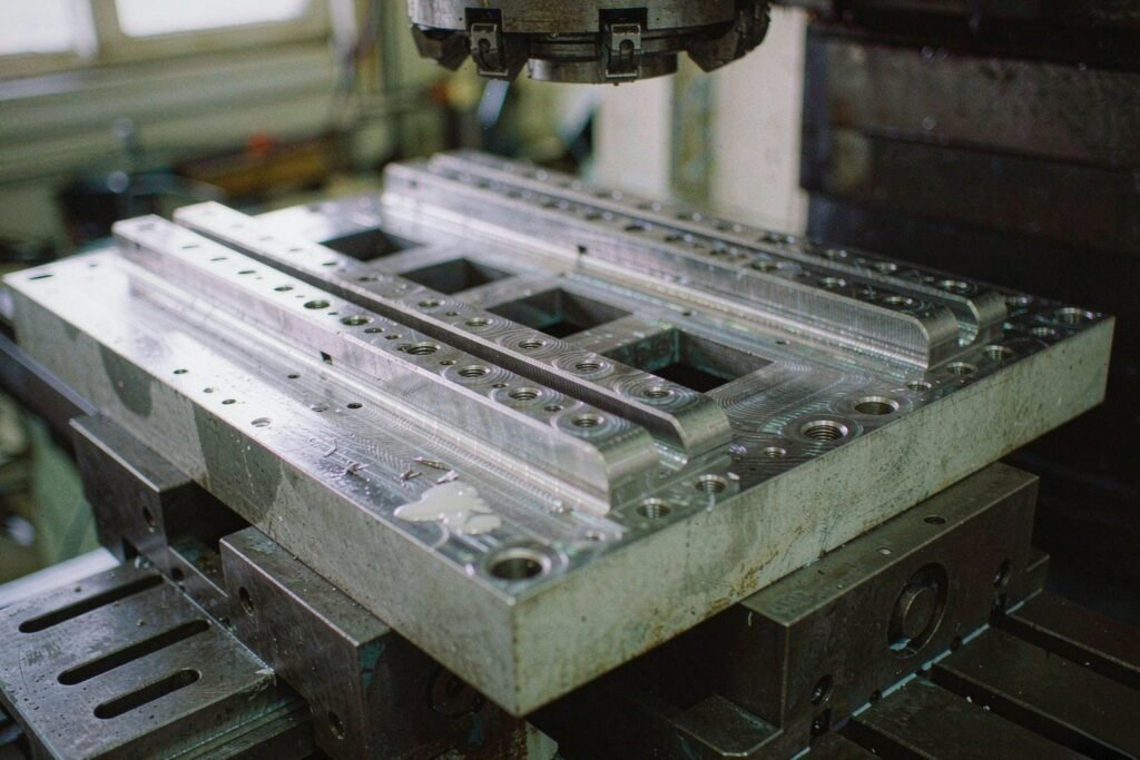
Two parallel seats, milled shoulders, tapped rows and a reamed dowel pair on a common datum.

Gusseted brackets with slotted and counterbored holes for sensor and motor mounts.

Bored bearing seats, snap-ring grooves and dowel pairs held as a set.
Answers before you send the drawing
What files do you need for a quote?
A STEP or IGES model is the quickest. Add a PDF of the drawing for tolerances, datums, surface finish and the material call-out, and say which faces are locating faces. If the finish value applies after coating, mark it that way on the drawing — we will flag it in the quote if it is ambiguous.
How do you hold flatness on a long base plate or frame?
XS Precision roughens long and thin parts, releases them, and finishes them in a second operation, with the finish cut taking a light, even allowance. Welded assemblies are stress-relieved before the mounting pad is milled. Flatness is then measured on the plate with an indicator on a granite reference and reported per part, with the value stated over a length so it can be compared with the rail it carries.
Can the rail seat and the bearing housing seat be cut in one set-up?
Yes, and on automated-equipment work we would rather do it that way. Both features are cut from a common datum in the same fixture, which removes the fixture-to-fixture error that otherwise shows up as an axis that binds at one end of travel. Where a part is too large for a single set-up, we agree in advance which face is the transfer datum and hold everything to it.
How do you handle anodising on tight-tolerance features?
The growth is planned, not ignored. Type II anodising adds roughly 5–25 µm per side and Type III hard anodising 25–75 µm, so bores, threads, press fits and mating faces are masked. Dimensions on the drawing are interpreted as finished dimensions, and where the tolerance is tighter than the coating can be controlled we machine an allowance and state it on the route.
What batch sizes do you take?
From a single prototype to a few hundred pieces per order. Prototypes and production run on the same fixture and the same programme, so the second order does not come back with a different set of numbers. Repeat orders are quoted against the original drawing revision, and we tell you if a revision has moved.
What documentation ships with the parts?
Material certificate (EN 10204 3.1 on request), a dimensional report covering the toleranced features, flatness and parallelism results where they were specified, a finish thickness record for coated parts, and photographs of the first article. Parts are packed so the finished faces arrive as they left the shop.
More detail on how these parts are made
Precision CNC machining
3-, 4- and 5-axis milling and turning for brackets, plates and frames, with the tolerance strategy explained.
High-precision components
Bored bearing seats, reamed dowel pairs and ground faces held to ±0.005 mm where the design needs it.
Material expertise
Aluminium, steel, stainless and engineering plastics, with the finish route and its dimensional effect for each.
Send the drawing. We will tell you where it will be expensive.
A STEP file, the material and the faces that matter are enough to start. Shenzhen XS Precision returns a price, a lead time and a note on any feature that will be hard to hold — before the first part is cut. NDA and drawing control are standard, and nothing made for one customer is ever shown to another.
ISO 2768-mK where the drawing is silent · first article report with photographs · repeat orders keep the same fixture and programme